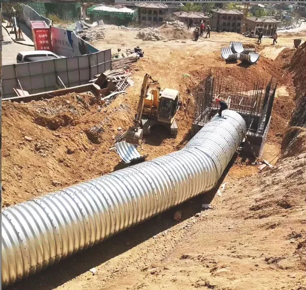

 Business License

Internal structure of rubber bearings (bridge seismic bearings)
# Internal Structure of Rubber Bearings (Bridge Seismic Bearings) Bridge seismic rubber bearings are core components that balance **load-bearing**, **displacement adaptation**, and **seismic energy dissipation** for bridge structures. Their internal structure is hierarchically designed around anti-seismic performance, integrating multi-layer rubber, reinforcing steel plates, and seismic-specific components to resist horizontal seismic forces while supporting vertical bridge loads. Below is a detailed breakdown of their internal composition and functional division:
## 1. Core Composite Layer: Foundation for Load-Bearing and Deformation This layer is the "backbone" of the bearing, responsible for transmitting vertical loads (e.g., bridge dead weight, vehicle loads) and adapting to small horizontal displacements (e.g., thermal expansion/contraction of the bridge). It consists of alternating **rubber layers** and **stiffening steel plates**, forming a "sandwich-like" composite structure.
### 1.1 Rubber Layers (Elastic Matrix) - **Material Selection**: - Ordinary seismic bearings: Natural rubber (NR) or chloroprene rubber (CR) (excellent elasticity, low-temperature resistance: -30℃ to 60℃). - Harsh-environment bearings (coastal, high-temperature areas): Ethylene-propylene-diene monomer (EPDM) rubber (resistant to salt spray, ozone, and high temperatures up to 120℃). - **Structural Characteristics**: - Thickness: 5–15 mm per layer (adjusted based on bearing height and displacement requirements). - Elastic Function: Under vertical loads, rubber deforms slightly to distribute pressure evenly; under horizontal forces (e.g., seismic activity), it undergoes shear deformation to absorb energy and adapt to bridge displacement. - **Key Performance**: Shear modulus (G) is controlled between 0.4–0.8 MPa (GB 20688.6-2006 standard), ensuring both flexibility (for displacement) and rigidity (for load-bearing). ### 1.2 Stiffening Steel Plates (Rigidity Reinforcement) - **Material**: Hot-rolled low-alloy high-strength steel (Q355B), with a thickness of 2–6 mm (thicker for large-load bearings). - **Processing**: - Surface treatment: Shot blasting (rust removal grade Sa2.5) + zinc plating (thickness ≥ 8 μm) to prevent corrosion between steel and rubber. - Bonding with rubber: Vulcanized at high temperature (140–160℃) and high pressure (10–15 MPa) to form a permanent bond (bond strength ≥ 10 MPa), avoiding delamination under shear. - **Functional Role**: - Restricts vertical deformation of rubber (prevents excessive compression under heavy loads), ensuring the bearing maintains stable height. - Transmits vertical loads from the bridge superstructure to the pier uniformly, avoiding local stress concentration on the pier.
## 2. Seismic Functional Layer: Core for Energy Dissipation and Shock Absorption This layer is unique to seismic bearings (distinguishing them from ordinary rubber bearings) and is designed to actively dissipate seismic energy, reducing the impact of earthquakes on the bridge. Common configurations include **lead-core inserts**, **high-damping rubber additives**, or **metal damping components**. ### 2.1 Lead-Core Seismic Component (for Lead-Rubber Bearings, LRB) - **Structure and Material**: - A solid lead cylinder (purity ≥ 99.9%) is vertically embedded in the center of the composite rubber-steel layer, with a diameter of 20–100 mm (matched to bearing size and seismic intensity). - The lead core is wrapped in a thin rubber sleeve to isolate it from the external environment and prevent oxidation.
- **Seismic Mechanism**: - Under small horizontal displacements (e.g., thermal deformation), the lead core remains rigid, ensuring the bearing’s stability. - During an earthquake (large horizontal displacement), the lead core undergoes **plastic deformation** (yield strength ~10 MPa), absorbing and dissipating a large amount of seismic energy (equivalent damping ratio ≥ 20%). - After the earthquake, the lead core retains partial elasticity, helping the bearing return to its original position (self-centering performance). ### 2.2 High-Damping Rubber Layer (for High-Damping Rubber Bearings, HDRB) - **Structure and Material**: - No independent metal core; instead, high-damping agents (e.g., carbon black, resin) are added to the rubber matrix (damping ratio ≥ 15%, 3–5 times that of ordinary rubber). - The composite layer still uses alternating rubber and steel plates, but the rubber itself acts as the energy-dissipating medium. - **Seismic Mechanism**: - During seismic shear deformation, the internal friction of the high-damping rubber (molecular chain friction) converts seismic kinetic energy into heat energy, achieving passive energy dissipation. - Suitable for medium-low seismic intensity areas (seismic fortification intensity ≤ 8 degrees) or bridges sensitive to lead pollution (e.g., drinking water source areas).
### 2.3 Auxiliary Seismic Reinforcements - **Anti-overturning Ribs**: Thin steel ribs (thickness 3–5 mm) added to the upper/lower edges of the composite layer to limit excessive horizontal displacement (preventing the bearing from sliding off the pier). - **Friction Damping Plates**: Stainless steel plates (304 grade) attached to the top/bottom of the bearing, paired with PTFE (polytetrafluoroethylene) sheets, reducing friction during horizontal displacement while providing secondary energy dissipation via friction.
## 3. Connection and Protection Layer: Ensuring Installation Stability and Durability This layer connects the bearing to the bridge superstructure and pier, while protecting the internal composite layer from environmental damage (e.g., water, dust, mechanical impact). ### 3.1 Upper and Lower Connecting Plates - **Material**: Thick steel plates (Q355B, thickness 10–30 mm), larger in area than the composite layer (extending 5–10 mm outward) to facilitate anchoring. - **Structure**: - Pre-drilled anchor bolt holes (diameter 16–30 mm) along the edge, matching the bolt size of the bridge beam and pier. - The inner surface (connected to the composite layer) is roughened (Ra 50–100 μm) and vulcanized with the top/bottom rubber layers to ensure integral force transmission. - **Function**: Transfer vertical/horizontal loads between the composite layer and the bridge/pier; provide a stable base for anchor installation.
### 3.2 Anchoring Components - **Anchor Bolts**: High-strength bolts (grade 8.8 or 10.9), made of 40Cr steel (heat-treated) or stainless steel (316 grade for coastal areas). - Upper bolts: Connect the bearing to the bridge beam’s bottom flange, with anti-loosening nuts (double nuts or lock washers). - Lower bolts: Fix the bearing to the pier’s top concrete (embedded in precast concrete sleeves), ensuring no relative sliding under seismic forces. - **Grouting Layer**: Epoxy mortar (compressive strength ≥ 60 MPa) filled between the lower connecting plate and the pier, leveling the installation surface and enhancing load transmission.
### 3.3 Protective Cover - **Material**: Chlorinated polyethylene (CPE) rubber or aluminum alloy (for heavy-duty bearings). - **Structure**: A cylindrical or rectangular cover that wraps the side of the composite layer, with a sealing ring (EPDM) at the top/bottom to prevent water, dust, or debris from entering the internal layers. - **Function**: Avoid rubber aging caused by UV radiation, prevent steel plate corrosion from rainwater, and extend the bearing’s service life (design life ≥ 50 years).
## 4. Synergistic Working Principle of Internal Structures During normal bridge operation and seismic events, all internal layers work together to achieve multi-functional protection: 1. **Normal Operation**: - Vertical loads (bridge weight, vehicles) are transmitted through the upper connecting plate → composite layer (rubber + steel plates) → lower connecting plate → pier. - Horizontal displacements (thermal expansion/contraction) are adapted by the shear deformation of the rubber layer, with the friction damping plate reducing movement resistance. 2. **Seismic Events**: - Horizontal seismic forces trigger shear deformation of the composite layer; the lead core (or high-damping rubber) undergoes plastic deformation/friction to dissipate energy. - Anti-overturning ribs limit excessive displacement, and anchor bolts prevent the bearing from detaching; the protective cover avoids secondary damage to internal components from falling debris. If needed, I can help you create a **detailed cross-sectional diagram of the seismic rubber bearing** (labeling rubber layers, steel plates, lead core, and connecting components) or a **material parameter comparison table** (for NR, CR, EPDM rubbers and Q355 steel) to visualize the internal structure more intuitively.
Recently Posted
-
Cost-Effectiveness and Long-Term Operation Value of Air Shield Dam Water Conservancy Facility
August 16, 2026For water conservancy investors and engineering contractors, air shield dams have obvious economic advantages in long-term project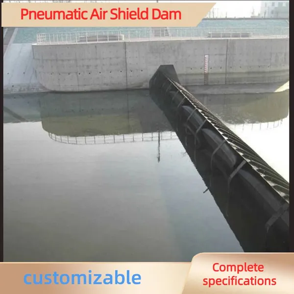 Read More
 -
Flood Control Performance and Safety Features of Modern Air Shield Dam
August 16, 2026Flood prevention and drainage are the core functions of river hydraulic facilities, and air shield dams show outstanding safety an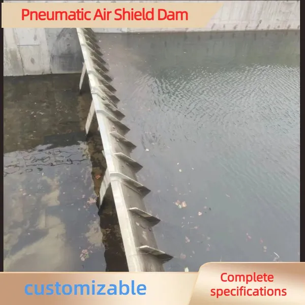 Read More
 -
How Air Shield Dam Improves River Ecological Environment and Protects Aquatic Ecology
August 16, 2026Traditional water retaining dams often block river migration channels and destroy the original ecological balance of water bodies. Read More
 -
Advantages of Pneumatic Air Shield Dam in Urban Landscape River Projects
August 16, 2026Urban landscape rivers require both practical water regulation functions and beautiful waterscape effects, and air shield dams per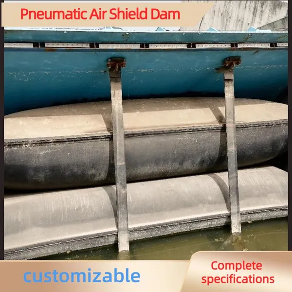 Read More

Contact Us
Recommended Products
-
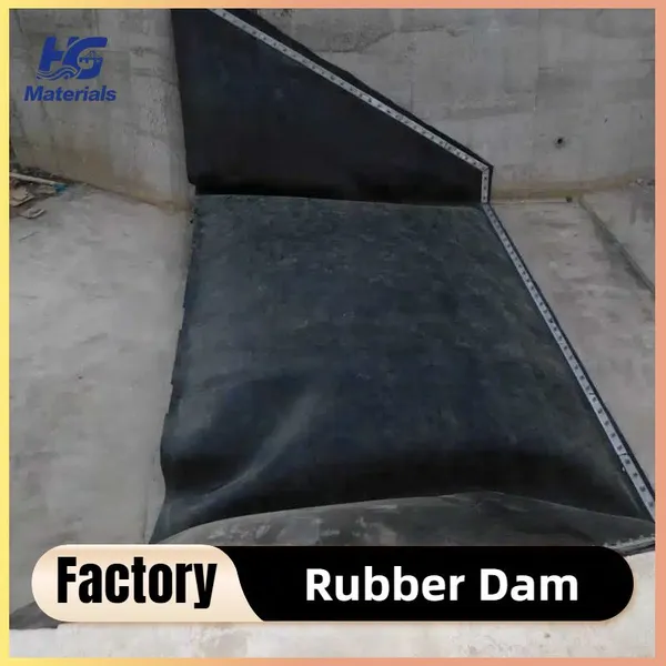
 Custom Inflatable Rubber Dams – Dual Protection for Flood Control & Irrigation, Direct Factory SupplyUS$ 170 - 250MOQ: 20 Meters
 -
Inflatable Rubber Dams for River Regulation – Specialized for Ecological Landscape Water Storage, Customizable on DemandUS$ 170 - 250MOQ: 20 Meters
-
Lightweight Inflatable Rubber Dams – Fast Deployment, Ideal for Emergency Water ManagemenUS$ 170 - 250MOQ: 20 Meters
-
The Rubber Dam Built for Farmland Irrigation in Indonesia Can Store Water in a 25-meter-wide River.US$ 170 - 250MOQ: 20 Meters
-
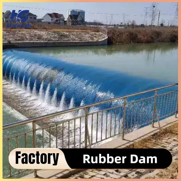
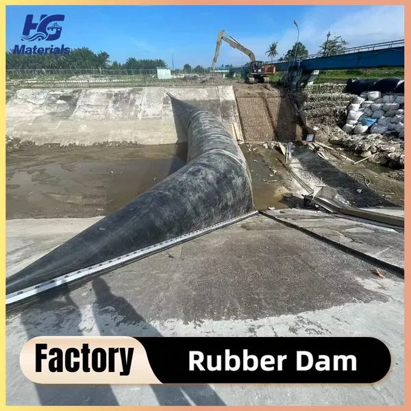
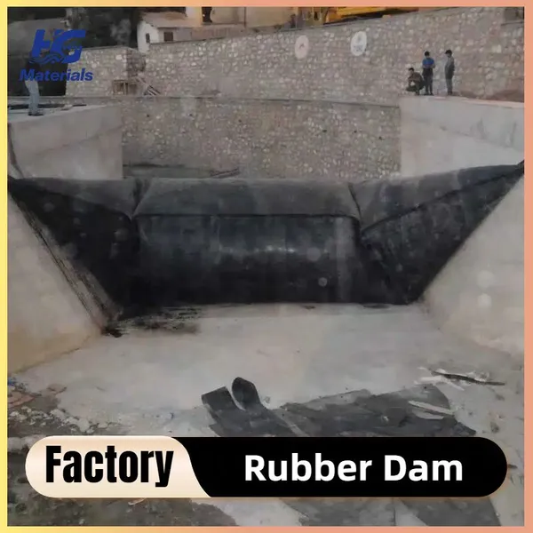
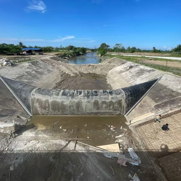
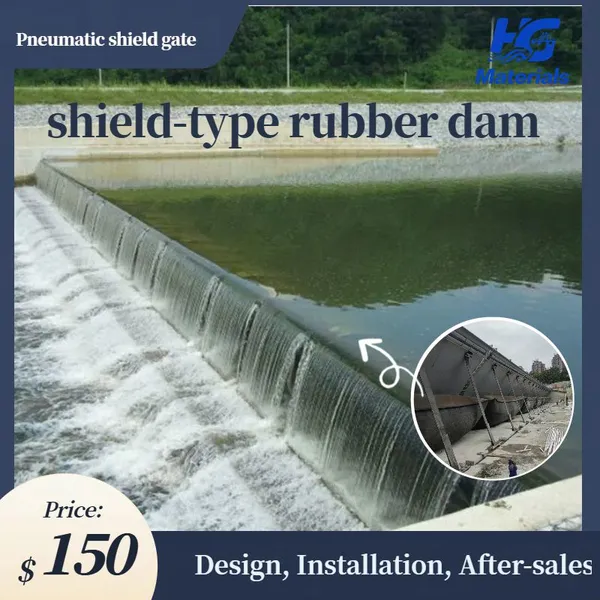
Pneumatic Shield Gate Shield-type Rubber Dam Air Shield Dam Spillway Gate Inflatable Rubber Dam Sold to Thailand, Malaysia, PhilippinesUS$ 1200 - 1500MOQ: 10 Square Meters
-
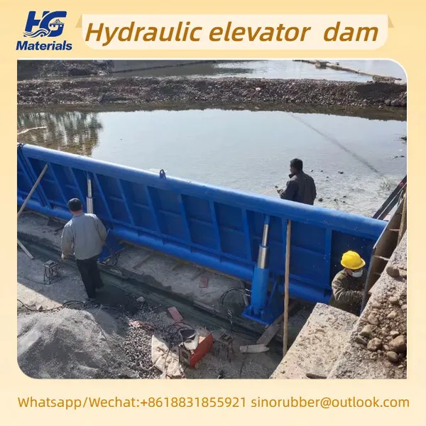
HG006 Hydraulic Elevator Dam Store Water Irrigate Landscape Flood Control Sluice Dam GateUS$ 300 - 350MOQ: 10 Square Meters
-
HG002 Cast Iron Sluice Gate, Farmland Irrigation and Drainage Gate, High-strength Wear-resistant Hydraulic Gate, Available in WholesaleUS$ 200 - 3000MOQ: 10 Combos
-
HG002manufacturer Specializes in Producing Custom-made Copper-inlaid Cast Iron Gates and Cast Iron Round GatesUS$ 200 - 3000MOQ: 10 Combos
-
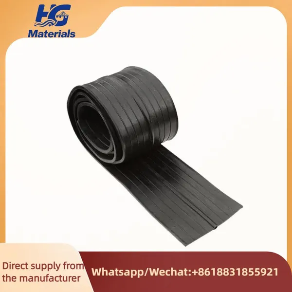
HG001 High Quality Rubber Pvc Water-stop Construction Concrete Joints Waterstops Rubber Water StopUS$ 4.8 - 5MOQ: 100 Meters
-
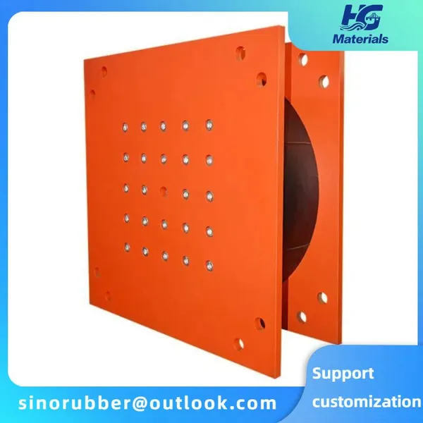
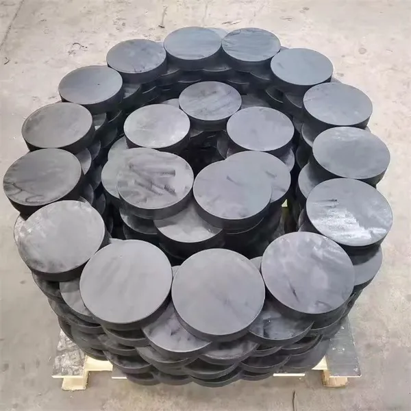
HG004 Elastomeric Laminated Neoprene Rubber Bridge Bearing Pad Nature Rubber Elastomeric Bearing PadUS$ 6.7 - 7MOQ: 10 Pieces
-
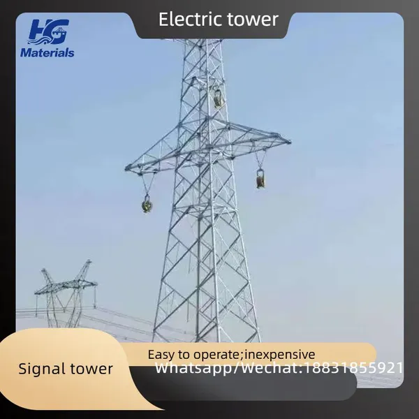
Iron Tower, Signal Tower, Power TowerUS$ 980 - 1000MOQ: 10 Metric Tons
-
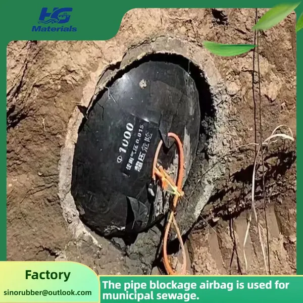
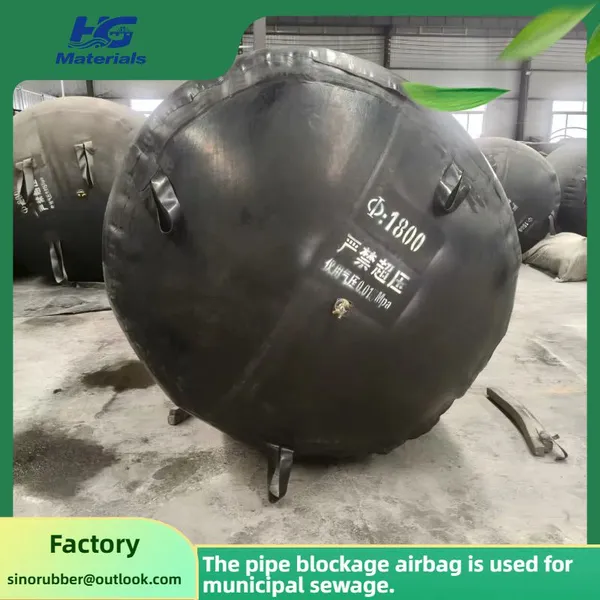
HG003 Customized Municipal Sewer Pipe Repair Pipe Blockage Diameter 800 Rubber Airbag Rubber Pipe Sealing AirbagUS$ 5 - 100MOQ: 10 Combos
-
Pipeline Blockage Water Balloon, Sewer Sewage Pipe Leak Sealing Rubber Balloon, Thickened Inflatable Pipeline BalloonUS$ 5 - 100MOQ: 10 Combos
-
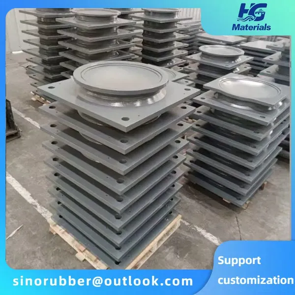
Bridge Rubber Bearings With Steel Reinforcement for Railway Use - Low Noise and Vibration Reduction PropertiesUS$ 6.7 - 7MOQ: 10 Pieces
-
HG004 Bridge Highway Rubber Bearings, Circular and Rectangular Bridge Construction PTFE Rubber Pad Bearings, Shock-absorbing PadsUS$ 6.7 - 7MOQ: 10 Pieces
-
Custom Inflatable Rubber Dams – Dual Protection for Flood Control & Irrigation, Direct From Source FactoryUS$ 170 - 250MOQ: 20 Meters
-
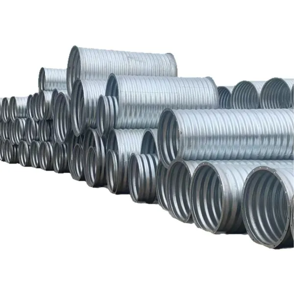
Hot Selling Galvanized 30 Corrugated Metal Pipe Cmp Culvert PipeUS$ 200 - 210MOQ: 100 Meters
-
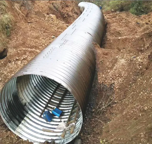
Galvanized Corrugated Metal Pipe 20mm 3/4'' Armco Mp100 Steel Pipe Flexible Corrugated Tube Large DiameterUS$ 200 - 210MOQ: 100 Meters
-
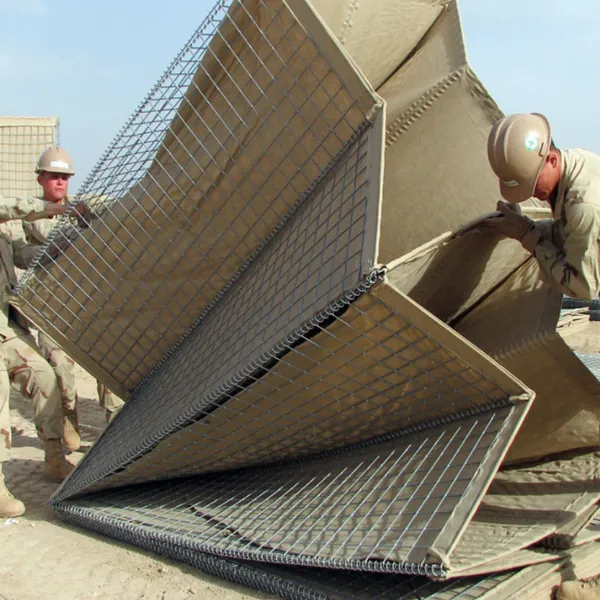
Hesco Bastion Galvanized Barrier Welded Barriers for Bastion Sand Recover Geotextile BastionUS$ 6 - 7MOQ: 100 Cases
-
Customizable Culvert Pipe Oval Shaped Steel Road Cheap 36 Inch Corrugated Metal Pipe PriceUS$ 200 - 210MOQ: 100 Meters