
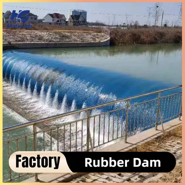
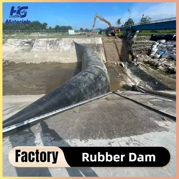
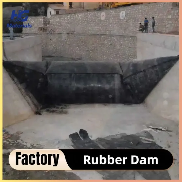
Installation process of inflatable rubber dams
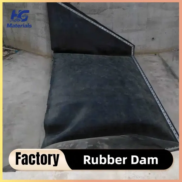
# Installation Process of Inflatable Rubber Dams Inflatable rubber dams are flexible hydraulic structures, and their installation requires strict adherence to engineering standards to ensure structural stability and operational reliability. The process is systematically divided into the following key phases: ## 1. Preliminary Preparation and Site Survey ### 1.1 Site Recheck - Verify the terrain, dimensions, and geological conditions (e.g., riverbed bearing capacity, flow velocity) of the river/channel against design drawings. Confirm the foundation construction scope and anchoring positions to avoid conflicts with underground pipelines or structures. - Assess the surrounding environment: Clear obstacles (e.g., rocks, tree stumps) within the construction area and check for potential flood risks during the installation period. ### 1.2 Material and Equipment Inspection - **Dam Bag Inspection**: Check the integrity of the rubber layer (neoprene or EPDM), the tensile strength of the fiber reinforcement layer (nylon/polyester), and the airtightness of seams (via visual checks and local pressure tests). - **Anchoring Components Check**: Verify the material (e.g., galvanized steel for bolts/plates) and dimensions of anchoring parts; ensure no corrosion or deformation. - **Inflation/Deflation System Test**: Test the performance of air compressors, blowers, control valves, pressure gauges, and sensors to confirm they meet design specifications. ## 2. Foundation Structure Construction The foundation serves as the load-bearing base for the dam and must be stable, flat, and compatible with the anchoring system. ### 2.1 Riverbed Preparation - Clear silt, debris, and sharp objects from the riverbed. For soft ground, conduct compaction or backfilling (using graded sand-gravel) to ensure the bearing capacity meets design requirements (typically ≥150 kPa). - Level the riverbed surface to an error of ≤3 mm to prevent damage to the dam bag. ### 2.2 Concrete Foundation Pouring - Pour reinforced concrete foundations (including the riverbed base and bank sidewalls) according to design requirements. Embed **anchoring grooves** (for fixing the dam bag edges) and pre-bury holes for inflation/deflation pipelines. - Smooth and finish the concrete surface to avoid sharp edges; cure the concrete until its strength reaches 100% of the design value (usually C25 or higher). ### 2.3 Pre-installation of Anchoring System - Install pre-embedded bolts and steel pressing plates in the anchoring grooves. Ensure bolt positions are accurate (error ≤±2 mm) and apply anti-corrosion treatment (e.g., galvanization or rust-proof paint). - Place rubber gaskets between the steel plates and dam bag to prevent direct metal-to-rubber friction. ## 3. Dam Bag Laying and Fixing The dam bag is the core water-retaining component, and its installation requires precision to avoid wrinkles or tears. ### 3.1 Dam Bag Unfolding and Inspection - Unfold the folded dam bag on a flat, clean temporary site (covered with canvas or rubber mats). Check for surface damage (scratches, holes) and confirm the correct orientation (the wear-resistant side faces the water flow). ### 3.2 Positioning and Hoisting - Use a crane or winch to lift the dam bag to the foundation. Align its centerline with the river’s centerline and lower it slowly to avoid dragging (which may abrade the rubber layer). - Adjust the dam bag to ensure even alignment with the anchoring grooves; eliminate wrinkles by gently stretching the edges. ### 3.3 Edge Anchoring - Embed the reinforced edges of the dam bag into the anchoring grooves. Cover with steel pressing plates and tighten the bolts **symmetrically and in stages**: 1. First, tighten bolts to 30% of the design torque to fix the dam bag position. 2. Then, increase torque to 70% and check for wrinkles or misalignment. 3. Finally, tighten to the full design torque (typically 30–50 N·m for M16 bolts) to ensure a tight seal and prevent displacement. - Fill gaps between the dam bag edges and anchoring grooves with waterproof sealant to enhance water tightness. ## 4. Installation of Inflation/Deflation System This system controls the dam’s elevation and must ensure unobstructed airflow and reliable operation. ### 4.1 Pipeline Connection - Connect the inflation pipeline (high-pressure rubber or steel pipes) to the dam bag’s air inlet valve and the air compressor/blower. Use flange joints with gaskets to prevent air leakage. - Install the deflation pipeline: Connect the dam bag’s air outlet valve to an exhaust port, and equip it with emergency deflation valves for rapid pressure release (e.g., during floods). ### 4.2 Equipment Installation and Calibration - Fix air compressors, control cabinets (with pressure sensors and solenoid valves), and pressure gauges in a weatherproof location. Ensure electrical connections are waterproof. - Calibrate pressure sensors and gauges to ensure accurate monitoring (error ≤±1% of the design pressure). Test valve opening/closing flexibility to avoid jamming. ## 5. Test Inflation and Commissioning This phase verifies the dam’s performance and system coordination before official operation. ### 5.1 Graded Inflation 1. **Initial Inflation**: Inflate the dam bag to 30% of the design working pressure (e.g., 0.03 MPa for a 0.1 MPa design pressure). Pause for 10–15 minutes to check for uniform expansion and edge displacement. 2. **Intermediate Inflation**: Increase pressure to 70% of the design value. Inspect for air leakage (using soapy water to check joints) and confirm the dam’s height aligns with design specifications (error ≤±5 cm). 3. **Full-Pressure Inflation**: Inflate to the design working pressure. Hold the pressure for 24 hours; a pressure drop of ≤5% is considered acceptable. ### 5.2 Water-Retention and Emergency Tests - Retain water upstream to the design water level. Check the dam’s stability against water pressure and inspect for leakage at the base and edges. - Conduct an emergency deflation test: Activate all exhaust valves and confirm the dam collapses completely within the design time (usually ≤10 minutes) to ensure it does not block flood discharge. ### 5.3 System Coordination Test - Test the automatic control function of the inflation/deflation system (e.g., automatic deflation when pressure exceeds the threshold). Verify that sensors and the control cabinet communicate effectively. ## 6. Acceptance and Trial Operation ### 6.1 Final Acceptance - A joint inspection by the design, construction, and supervision teams is required to verify: - Foundation strength and flatness. - Dam bag anchoring quality and airtightness. - Inflation/deflation system performance. - Water-retaining and emergency response capabilities. - Sign the acceptance certificate only if all indicators meet the *Technical Code for Rubber Dams* (SL 227-98). ### 6.2 Trial Operation and Training - Conduct a 1–3 month trial operation. Record operational data (e.g., pressure, dam height, water level) under different conditions to confirm long-term stability. - Train operators on inflation/deflation operations, pressure monitoring, and troubleshooting (e.g., handling minor air leaks). ## Key Notes - Avoid installation during extreme weather (heavy rain, strong winds, or temperatures below -5℃) to prevent damage to the dam bag. - Protect the dam bag from sharp objects during transportation and laying; use talcum powder to reduce friction between the dam bag and foundation. - After installation, regularly inspect the anchoring bolts and sealant to maintain long-term operational safety. Would you like me to create a **simplified on-site operation checklist** for this installation process to make on-site verification more efficient?
Recently Posted
-
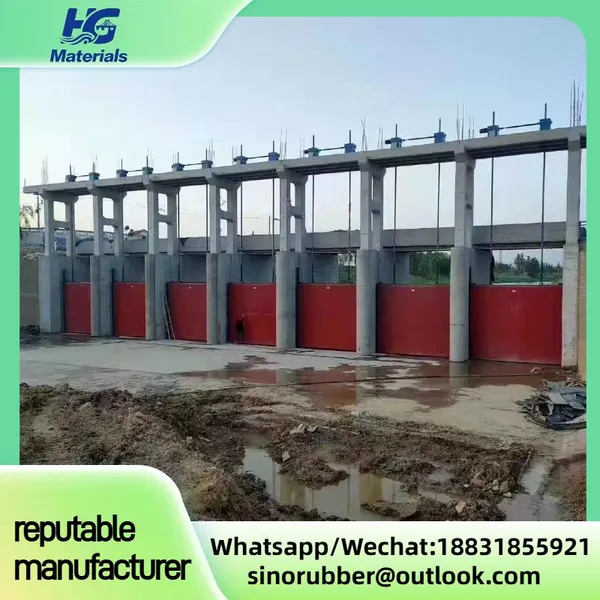
Quality inspection process of steel sluice gates
March 8, 2026Quality Inspection Process of Steel Sluice Gates1. Raw Material InspectionCheck material certificates (MTC) for steel plates, prof Read More
 -
Production process of steel gate
March 8, 2026Production Process of Steel Gate (Sluice Gate)This is the standard industrial production flow for steel gates / steel sluice gates Read More
 -
Applications of steel gates
March 8, 2026Steel gates (also called steel sluice gates / penstocks) are widely used for water flow control, isolation, and water level regula Read More
 -
The Uses of Steel Gate Valves
March 8, 2026Steel gate valves are primarily used for full shut-off/isolation in high-pressure, high-temperature, and heavy-duty industrial sys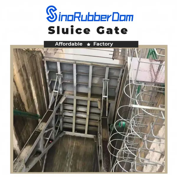 Read More

Contact Us
Recommended Products
-
 Custom Inflatable Rubber Dams – Dual Protection for Flood Control & Irrigation, Direct Factory SupplyUS$ 170 - 250MOQ: 20 Meters
 -
Inflatable Rubber Dams for River Regulation – Specialized for Ecological Landscape Water Storage, Customizable on DemandUS$ 170 - 250MOQ: 20 Meters
-
Lightweight Inflatable Rubber Dams – Fast Deployment, Ideal for Emergency Water ManagemenUS$ 170 - 250MOQ: 20 Meters
-
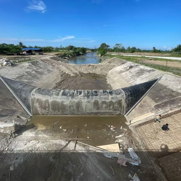
The Rubber Dam Built for Farmland Irrigation in Indonesia Can Store Water in a 25-meter-wide River.US$ 170 - 250MOQ: 20 Meters
-
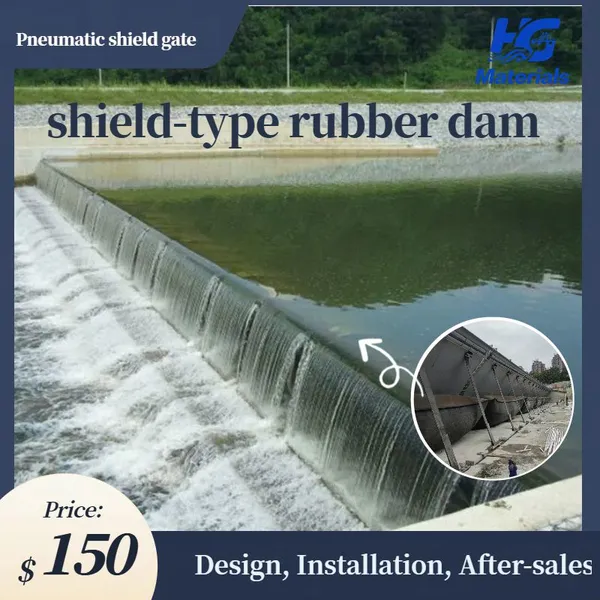
Pneumatic Shield Gate Shield-type Rubber Dam Air Shield Dam Spillway Gate Inflatable Rubber Dam Sold to Thailand, Malaysia, PhilippinesUS$ 1200 - 1500MOQ: 10 Square Meters
-
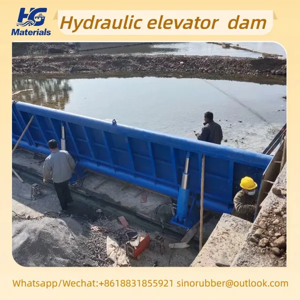
HG006 Hydraulic Elevator Dam Store Water Irrigate Landscape Flood Control Sluice Dam GateUS$ 300 - 350MOQ: 10 Square Meters
-
HG002 Cast Iron Sluice Gate, Farmland Irrigation and Drainage Gate, High-strength Wear-resistant Hydraulic Gate, Available in WholesaleUS$ 200 - 3000MOQ: 10 Combos
-
HG002manufacturer Specializes in Producing Custom-made Copper-inlaid Cast Iron Gates and Cast Iron Round GatesUS$ 200 - 3000MOQ: 10 Combos
-
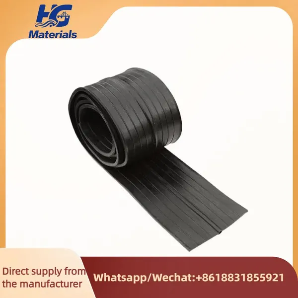
HG001 High Quality Rubber Pvc Water-stop Construction Concrete Joints Waterstops Rubber Water StopUS$ 4.8 - 5MOQ: 100 Meters
-
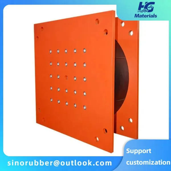
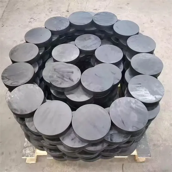
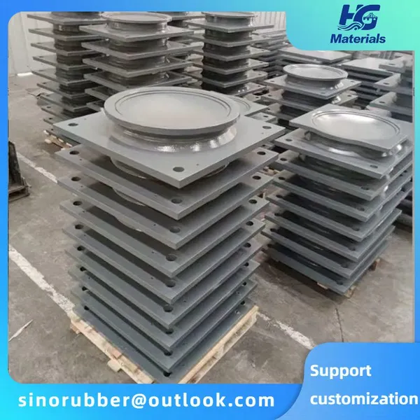
HG004 Elastomeric Laminated Neoprene Rubber Bridge Bearing Pad Nature Rubber Elastomeric Bearing PadUS$ 6.7 - 7MOQ: 10 Pieces
-
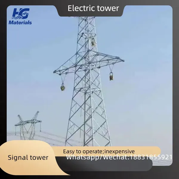
Iron Tower, Signal Tower, Power TowerUS$ 980 - 1000MOQ: 10 Metric Tons
-
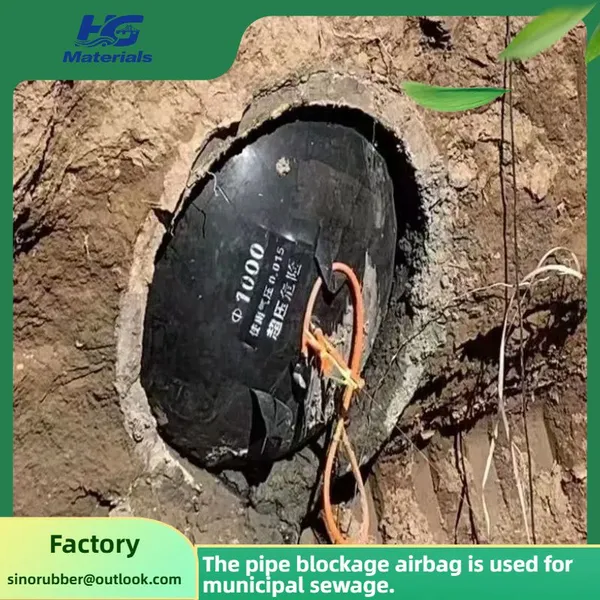
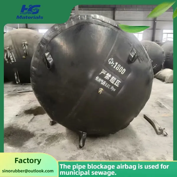
HG003 Customized Municipal Sewer Pipe Repair Pipe Blockage Diameter 800 Rubber Airbag Rubber Pipe Sealing AirbagUS$ 5 - 100MOQ: 10 Combos
-
Pipeline Blockage Water Balloon, Sewer Sewage Pipe Leak Sealing Rubber Balloon, Thickened Inflatable Pipeline BalloonUS$ 5 - 100MOQ: 10 Combos
-
Bridge Rubber Bearings With Steel Reinforcement for Railway Use - Low Noise and Vibration Reduction PropertiesUS$ 6.7 - 7MOQ: 10 Pieces
-
HG004 Bridge Highway Rubber Bearings, Circular and Rectangular Bridge Construction PTFE Rubber Pad Bearings, Shock-absorbing PadsUS$ 6.7 - 7MOQ: 10 Pieces
-
Custom Inflatable Rubber Dams – Dual Protection for Flood Control & Irrigation, Direct From Source FactoryUS$ 170 - 250MOQ: 20 Meters
-
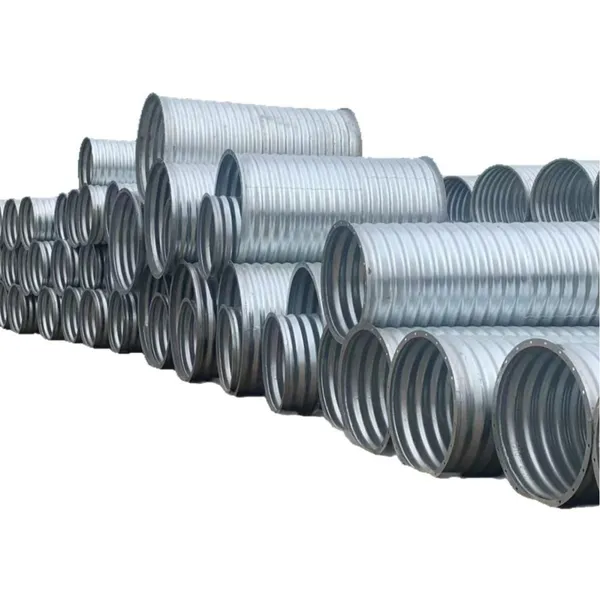
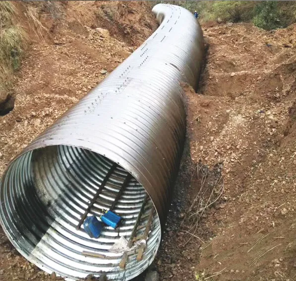
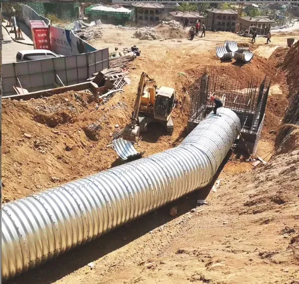
Hot Selling Galvanized 30 Corrugated Metal Pipe Cmp Culvert PipeUS$ 200 - 210MOQ: 100 Meters
-
Galvanized Corrugated Metal Pipe 20mm 3/4'' Armco Mp100 Steel Pipe Flexible Corrugated Tube Large DiameterUS$ 200 - 210MOQ: 100 Meters
-
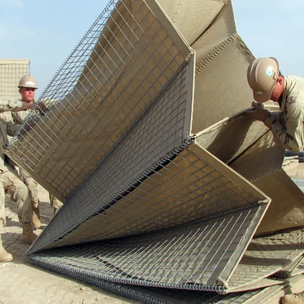
Hesco Bastion Galvanized Barrier Welded Barriers for Bastion Sand Recover Geotextile BastionUS$ 6 - 7MOQ: 100 Cases
-
Customizable Culvert Pipe Oval Shaped Steel Road Cheap 36 Inch Corrugated Metal Pipe PriceUS$ 200 - 210MOQ: 100 Meters